2020.06.25
How ALMA Works Vol. 2: Combining Multiple Antennas into One Radio Interferometer
── In the previous interview, we have learned that a larger telescope can achieve better performance in terms of the ability to see a darker object as well as the ability to look into further details of an object.
Hiramatsu: Right. While astronomers wish to have a larger diameter telescope, there are limitations in the size of a single telescope. Then, they came up with an idea of making a single giant telescope called “radio interferometer” by combining multiple telescopes.
Hiramatsu: Although there have been developed various types of radio telescopes, it was Martin Ryle at the University of Cambridge, UK, that provided the basis for the modern radio interferometers like ALMA by a revolutionary invention. He was awarded the Nobel Prize in Physics in 1974 for this invention. It was extraordinary research that had a big impact on astronomy.
── As for the concept of “combining multiple telescopes into one,” even though I only have a vague image, it’s understandable to a degree. However, I’m still having a hard time understanding why the performance of a telescope is improved by combining multiple telescopes. Can you explain how it works?
Hiramatsu: For example, ALMA consists of 66 antennas. In operations, every two antennas are paired up. So, let’s think about the case of a pair of antennas. Signals received by each of the two antennas are sent to a dedicated supercomputer called the “correlator”. An important point here is the time of the radio signals of the target object arriving at the two antennas.
Imagine the two antennas that are observing the same celestial object. When the object is right in front of the two antennas, the radio signals from the object reach the two antennas at the same time.
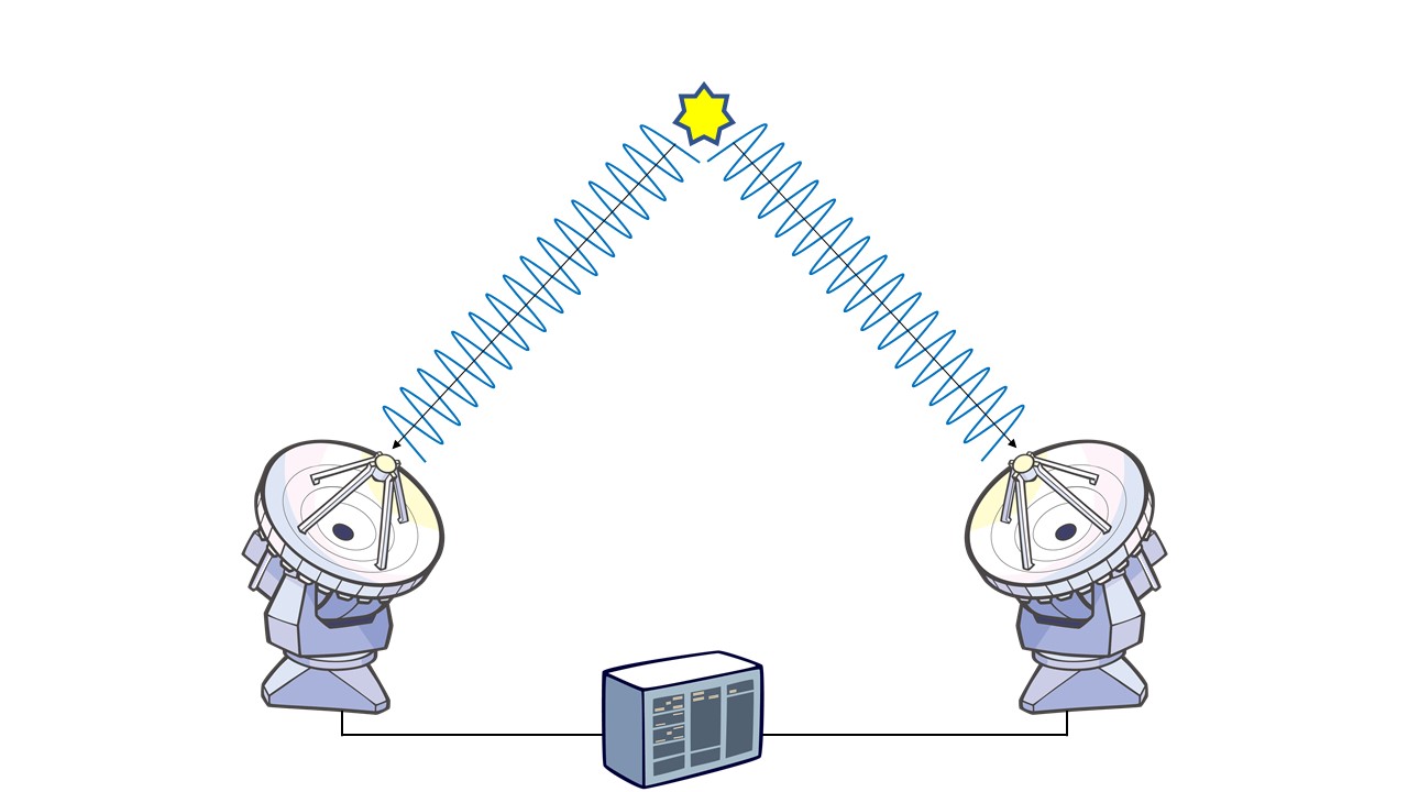
Figure 1. When the target object is right in front of the two antennas
Credit: ALMA (ESO/NAOJ/NRAO)
On the other hand, when the target object is at a slightly inclined position from the antennas, the radio signals arrive at each antenna with a slight time difference.
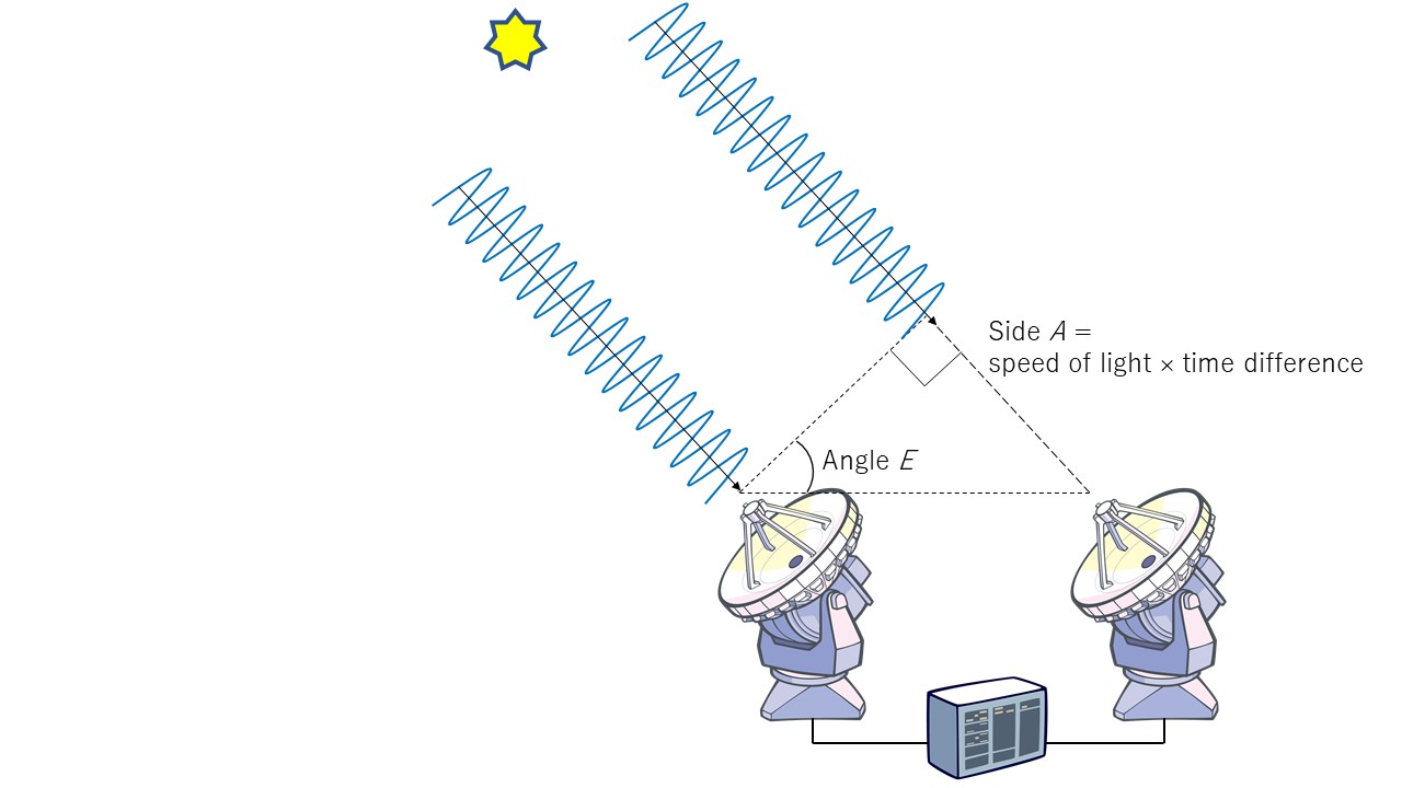
Figure 2. When the target object is at a slightly inclined position from the antennas
Credit: ALMA (ESO/NAOJ/NRAO)
── In this figure, the left antenna receives the radio signal first.
Hiramatsu: Correct. The radio signals reach the right antenna with a short time delay. Now, you can see a right triangle between the two antennas. The length of the side A is calculated by multiplying the speed of light by the difference of arrival time of the radio signals. We can obtain the distance between the two antennas by measurement. Now the length of the two sides are obtained, then we can derive the angle E with trigonometric function. The angle E represents the direction of the object from the position of the antennas.
What happens if the target object is located at a different position?

Figure 3. When the target object is located at a different position from Figure 2.
Credit: ALMA (ESO/NAOJ/NRAO)
In Figure 3, as the position of the target object is slightly shifted from the position in Figure 2, there is a small change in the arrival time of the radio signals at the two antennas. Consequently, the shape of the right triangle slightly changes along with a change in the angle E (corresponding to the angle e in the Figure 3). The point is, now we can identify the location of the radio source by measuring the time difference of the radio signals arriving at the two antennas. This function is performed by the correlator, which receives the signals from the two antennas, make a comparison, and measure the time difference between the two antennas.
── I see. This means, if we have two antennas, we can make a radio interferometer. Is that correct?
Hiramatsu: I can say that’s correct, but there is one more thing I should explain. What do you think the time difference would be when the target object is located at a position as shown in the figure below?
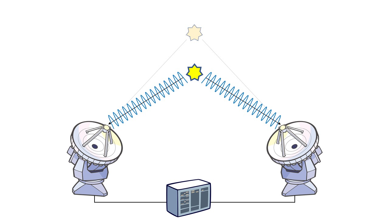
Figure 4. When the target object is right in front of the two antennas but at a lower position than Figure 1
Credit: ALMA (ESO/NAOJ/NRAO)
── Well…the two antennas receive the signals at the same time.
Hiramatsu: Right. The radio signals reach the antennas at the same time as seen in Figure 1. That means we are not able to distinguish the two locations, which are clearly different in Figures 1 and 4, from the arrival time of the radio signals.
── You’re saying we cannot locate where the radio source is coming from?
Hiramatsu: Right. If there is no difference in the arrival time, we cannot pinpoint the location of the radio source.
What is the solution for this? The answer is to place an additional antenna as shown below. Although there was no difference in the arrival time between the two antennas in Figure 2, we can make another right triangle between the left antenna and the new additional antenna that generates a time difference as shown in the figure below.
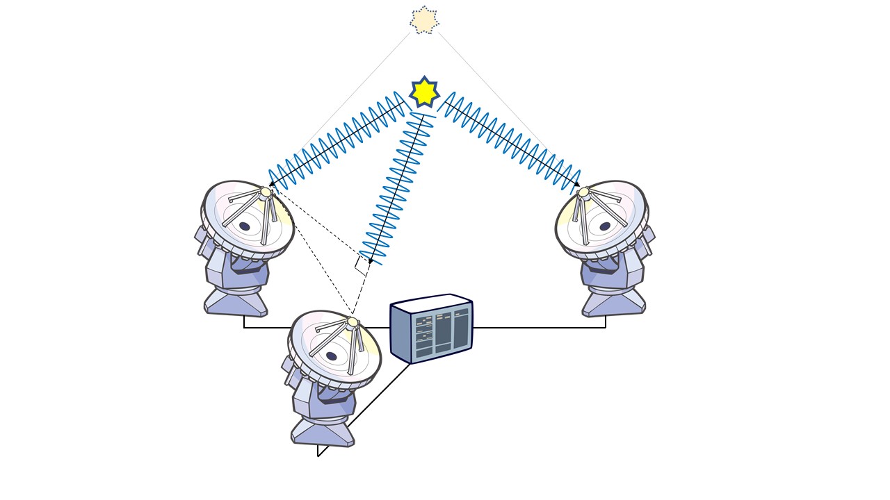
Figure 5. When three antennas are used.
Credit: ALMA (ESO/NAOJ/NRAO)
── I see, by increasing the number of antennas, we can measure the time difference in a different direction.
Hiramatsu: Exactly. For a review, please take a look at our short video that summarizes what we have learned so far. You can feel the sense of depth as you watch this three-dimensional CG.
Hiramatsu: In addition to increasing the number of antennas, there is another smarter way. Imagine that you see the antennas on the Earth from a target object. The position of the antenna looks like moving every moment as the Earth rotates. So, if we conduct an observation for a longer time, we can virtually make a larger number of antenna pairs available for the observation.

Figure 6. Schematic illustration of the antenna pair changing its position as the Earth rotates, as seen from the viewpoint of the target object. As the Earth rotates from the left figure to the right figure, the angle of the line connecting the two antennas changes. In other words, you can measure the time difference in different directions using only two antennas.
Credit: ALMA (ESO/NAOJ/NRAO)
── This method takes advantage of the effect of the Earth’s rotation. What a grandiose scheme.
Hiramatsu: By measuring the time difference with antenna pairs in various directions in this way, we can identify where in the sky radio sources are located, or in other words, we can visualize the distribution of radio sources. Obtaining a distribution map of radio sources is just like taking a “radio photo”. We can reveal the entire picture of the target object by collecting various data of time differences with multiple antenna pairs.
The ALMA antenna configuration is a good example that utilizes the antenna pairs in various directions.

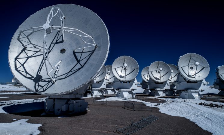
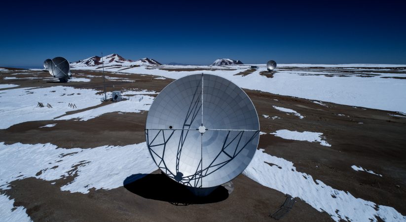
Figure 7. Actual ALMA antenna configuration
Credit: ALMA (ESO/NAOJ/NRAO), A. Marinkovic/X-Cam
── Apparently, it doesn’t look like having any regular patterns in the antenna configuration.
Hiramatsu: You hit the right nail on the head. If the antennas are arranged regularly in a grid pattern, they will have the same intervals and the same directions. In such a configuration, we measure the same time differences and only obtain overlapped data. So, we need to arrange the antennas with slightly changed intervals and directions. It might look like a random configuration, but we can say it’s “precisely calculated randomness”. To produce the best composite radio image, we determine in advance how the antennas are configured.
── I see. It looks like just a random arrangement, but it actually is a well-thought-out antenna configuration. Well, I can see a group of antennas standing very close to each other in a small area in the front of the photo. Is there any purpose for this compact configuration?
Hiramatsu: Yes. By having a larger space between the antennas, we can measure the smaller time difference. More specifically, it enables us to detect even a very small difference in the position of the target object. Making the antenna spacing larger leads to a higher resolution. As I explained earlier, the larger the diameter of the telescope, the higher the resolution. The same applies to the interferometer. As we have a larger space between the antennas, we can achieve higher resolution.
── If that is the case, I think the antennas should be arranged far away from each other, instead of being concentrated.
Hiramatsu: When the antennas are stretched out, there is a decrease in the ability to capture an extended structure in return for an increase in the resolution. To observe an extended object, we need a compact antenna configuration. You can see the Atacama Compact Array (nicknamed Morita Array) developed by NAOJ in the front of the photo. The antennas are concentrated in a compact area for observation of an extended object.
── I’m afraid that they might bump into each other as the spacing is so small.
Hiramatsu: We must keep a sufficient space between the antennas for crash prevention. For example, the 12-m antenna is not allowed to stand within 15 m from other antennas to avoid a collision. Then, to make a more compact configuration, we need a smaller 7-m antenna. It enables us to see more extended structures that cannot be observed merely by the array of 12-m antennas. However, even in the case of the 7-m antennas, we cannot make the antenna spacing smaller than 9 m.
── If so, isn’t it possible to capture further extended structures even with the 7-m antennas?
Hiramatsu: Then, it’s the turn of the Morita Array’s12-m antenna to demonstrate its capability.
── If my memory is correct, the 12-m antennas cannot be closer than 15 m from each other.
Hiramatsu: Right. If they are used as part of the interferometer, the 12-m antennas cannot be closer than 15 m from each other. However, the four ACA 12-m antennas in the Morita Array do not form an interferometer.
── What do you mean by that?
Hiramatsu: They are stand-alone antennas that individually obtain data with no combination with other antennas. This observation method is called “single-dish observation”. Since the 12-m antenna has a single seamless reflector (dish), it is capable of capturing data with a diameter equivalent to the 0-m spacing to 12 m in the single-dish mode. I said earlier that the 7-m antennas are not able to capture data with an antenna spacing shorter than 9 m. As an alternative, we carry out a single-dish observation using the 12-m antennas in the Morita Array to obtain data that requires a shorter antenna spacing.
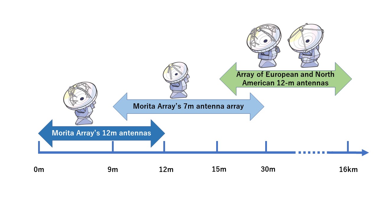
Figure 8. Schematic illustration of data obtained by three types of ALMA antennas. The horizontal axis shows the spacing between the antennas. As the antenna spacing of the European and North American 12-m antennas is larger than 15 m, they can capture data in the outer edge (from 15 m to 16 km). As the antenna spacing of the Japanese 7-m antenna is 9 m to 30 m, it has the capability to capture the data in that range. With the seamless reflector, the Japanese 12-m antenna in the Morita Array covers the data that ranges from 0 m to 12 m.
Credit: ALMA (ESO/NAOJ/NRAO)
── I had knowledge that ALMA has several types of antennas, but I didn’t know they have such distinctive characteristics.
Hiramatsu: ALMA has two arrays of antennas: one is the array of fifty 12-m antennas developed by the European and North American teams, and another is the array of the Japanese 7-m antennas. By combining the data obtained by these two arrays with the single-dish observation data obtained by the Japanese stand-alone 12-m antennas, ALMA achieves versatile capabilities that cover the observation of extended structures (taking of data with a small antenna spacing) as well as the observation of detailed structures at extremely high resolution (taking of data with a large antenna spacing).
── I see. Now I understand that various adjustments are needed for observations, which are not limited to making the antenna spacing larger.
Hiramatsu: Each researcher has a different preference according to the properties of the target object. While some researchers place priority particularly on high resolution, other researchers wish to capture the entire picture of an extended structure even at a moderate level of resolution. The three types of ALMA antennas offer the functionalities to respond to such a wide variety of requests.
── The Morita Array was developed by NAOJ, but is it used not only by Japanese researchers but also by researchers in Europe and North America? In the same way, Japanese researchers can use the array of the 12-m antennas developed by the European and North American teams?
Hiramatsu: Yes. We divided the development of the telescope by regions, but in operations, we share every part of the telescope and use it regardless of nationality. Our focus is placed on each individual researcher’s proposal that specifies what is the target object and how the observation is carried out.
── Thank you for taking time for this interview. I feel I have become more knowledgeable about how ALMA works.
Hiramatsu: I’m glad to hear that. Let’s carry this momentum to the next step. We will see how an actual observation is conducted next time. We are undertaking various efforts to ensure the reliability of the ALMA observation data and make it available to researchers.