Bienvenido a ALMA! INDEX
- 01. NAOJ ALMA Website Renewed !
- 02. Antenna Development and Culture Shock
- 03. Antenna Evaluation at the OSF
-
04. Bands 4 and 8 Received First Spectrum!\___SIMPLE_HTML_DOM__VOKU__AT____
- 05. Development of Band 4/8 Receivers
- 06. Band 10 Receiver Development
- 07. Dancing IZAYOI
- 08. ACA Software Development & First Fringes with ACA Correlator
- 09. Development of ALMA Data Analysis Software
- 10. Antenna Control Software Development & Simulated Observation
- 11. Making Unprecedented Telescope with People around the World
- 12. Commissioning ALMA with People around the World NOW
- 13. Daily Meeting with JAO & Project Coordination
- 14. Backstage of the ALMA Project
- 15. Early Science Operations Start!
- 16. ALMA Operations Start! Forecasting Future Galactic Observation Outcomes
- 17. ALMA Operations Start! ALMA Reveals Galaxy Formation and Evolution of the Universe!
- 18. Exploring the Origin of Life with ALMA
- 19. ALMA del Sol
- 20. Polarization Observations with ALMA
02. Antenna Development and Culture Shock
Published in the July 2010 issue of NAOJ News (monthly newsletter)
In February 2005, I was appointed as the leader of the NAOJ ALMA Antenna Team whose mission is developing and manufacturing four 12-m antennas and twelve 7-m antennas composing the Atacama Compact Array (ACA) as part of Japanese contributions to ALMA. The ACA 7-m antennas, which allow more compact configuration than the ALMA 12-m antenna array, are suitable for mapping of extended structures, while the ACA 12-m antennas are mainly used as single dish telescopes to capture more extended structures that are unobservable with the ALMA 12-m antennas or with the ACA 7-m interferometer.
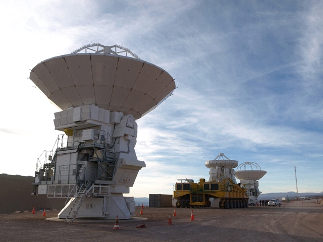
Figure 1: ACA 12-m antenna (front) and ACA 7-m antenna on the transporter (back). The 7-m antenna looks like a robot, since its main reflector is mounted on the big yoke structure which is nearly the same size as that of the 12-m antenna. At present, the first 7-m antenna has just arrived at the Operations Support Facility (OSF).
The technical requirements for the ACA antenna are very strict, because it will be operated in extremely harsh conditions. As you may know, the radio telescope performs observation any time day or night without protection against external environment (unlike an optical telescope that is shielded by a dome structure). This means the radio telescope continues observation even under the scorching sun, or in strong winds, except when the wind velocity is beyond the specified range. The ACA antenna needs to satisfy surprisingly high technical requirements under the environmental condition with the wind velocity of 6 m/s (with solar radiation) or 9 m/s (without solar radiation). Besides, the specifications of ALMA are defined not as best values obtained in a best possible condition, but as normal operating conditions.
Here, I will explain the technical requirements of the ACA 12-m antenna. First is tracking accuracy. The ACA 12-m antenna tracks the target object with an accuracy of 0.6 arcseconds (1 arcsecond corresponds to 1/3600 degrees) or better. Such a high accuracy is needed to obtain highly-reliable radio images with a combination of the ALMA interferometer and single-dish antennas. The surface accuracy of the ACA antenna is below 25 ?m including the measurement error of 10 ?m. In spite of this rigorous requirement, the completed ACA 12-m antenna has already achieved the surface accuracy of 7.4 ?m, which would be the best performance ever achieved by a millimeter/submillimeter telescope. However, this record is likely to be broken by the ACA 7-m antenna this year.
Another outstanding feature of the ACA antenna is the high-speed driving with a linear motor driving system. This mechanism is the same as the one that was adopted by the Subaru Telescope. The maximum driving velocity of the ACA antenna is 6 degrees per second in the azimuth direction and 3 degrees per second in the elevation direction: about 10 times faster than the 10-m telescopes of the Nobeyama Millimeter Array. The driving speed of the ACA antenna is really surprising and I experienced something like a culture shock when I saw it for the first time.
Another difficulty in the antenna development comes from the ALMA’s capability for the solar observations. Normally, radio telescopes, except a few for special purposes, do not observe the Sun or even avoid the direction close to the Sun for safety reason. Since the radio telescope is not protected by the dome-like structure unlike the optical telescope, the subreflector is highly heated by the collected sunlight and might catch a fire, if the telescope is directed to a position close to the Sun. In fact, there was an incident where a fire broke out from the cable connecting to the subreflector of a telescope overseas. The ACA antenna has a special surface to scatter visible light and collect radio waves only. I think the ACA antenna directed to the Sun is really beautiful.
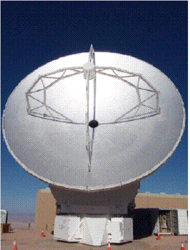
Figure 2: The ACA 12-m antenna directed to the Sun (at the OSF)
As ALMA is an international project, we need to control the antenna design and manufacturing process in accordance with the international standards of product assurance, safety, and Electromagnetic Compatibility (EMC). My task as the antenna team leader was to understand these standards (this is a really tough job), and then find out how to apply them to the actual antenna design. Thanks to all the people who had supported me, I managed to find a way through long and extensive discussions.
When the antenna design was fixed after great effort and struggle, we held the design review in Mitaka inviting reviewers including antenna specialists and engineers to check the antenna interfaces. At the design review, the reviewers pointed out technical risks and interface problems in detail, and presented many action items. We addressed these action items together with the antenna manufacturer and solved difficult problems one by one. As a result of our persistent efforts, the first 12-m antenna was finally handed over to NAOJ in 2007. During these periods, I was really busy with a pile of e-mails, many phone calls, and meetings, and had to frequently leave the office late at night. While going home on the last train, I had a feeling of fellowship because the train was always crowded with people who had just finished working just like me.
I led the NAOJ ALMA Antenna Team from 2005 to 2006. Our team at the time included many highly competent persons such as Ukita-san, Ezawa-san, Ikenoue-san, Inatani-san, and Yamada-san. Although I was a young and hasty team leader, they always gave me encouragement and support. I would like to close this article by expressing my appreciation for the support of all those involved in the ALMA project all over the world.
*The titles of authors and the names of organizations are those at the time of writing.